Ultrasonic Dog Chaser with Repelling Strobe Light and Extra Functions
Author: Irena Antoniuk, Technical Documentation Apps Engineer, Renesas Electronics Cover photo: www.depositphotos.com Introduction This article aims to demonstrate how to design a dog chaser. The system is designed using the HVPAK™ SLG47105V macrocells and other internal and external components within the GreenPAK to control a piezo element and a 3W LED.
Author: Irena Antoniuk, Technical Documentation Apps Engineer, Renesas Electronics
Cover photo: www.depositphotos.com
Introduction
This article aims to demonstrate how to design a dog chaser. The system is designed using the HVPAK™ SLG47105V macrocells and other internal and external components within the GreenPAK to control a piezo element and a 3W LED.
The Dog Chaser has three modes: Dog Repeller, Dog Training, and Flashlight. In the Dog Repeller mode, a powerful ultrasonic signal and a strobe light disorient the dogs. In the Dog Training mode, the lower power ultrasonic signal is used, this signal makes dogs annoyed, but not disoriented. The Flashlight mode is just a powerful flashlight that can be useful when additional lighting is needed.
1. Block Diagram and Circuit Design
The Block Diagram is shown in Figure 1.
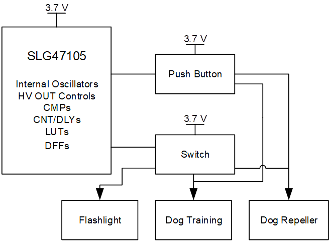
As can be seen in Figure 1, the Dog Chaser contains three modes, which are selected by a switch. Dog Repeller or Dog Training Mode is ON when the switch is in the appropriate position and the push button is pressed. To turn ON the Flashlight, there is no need to press the button, just switch to Flashlight Mode. The device is considered turned off when the switch is in the middle position (Dog Training Mode) and the push button is not pressed.
The circuit is powered by a Li-ion battery, so the VDD is between 3.0 V and 4.2 V. The LED intensity depends on voltage VDD, so the DC-DC Boost Converter is added to provide the constant necessary current to the LED.
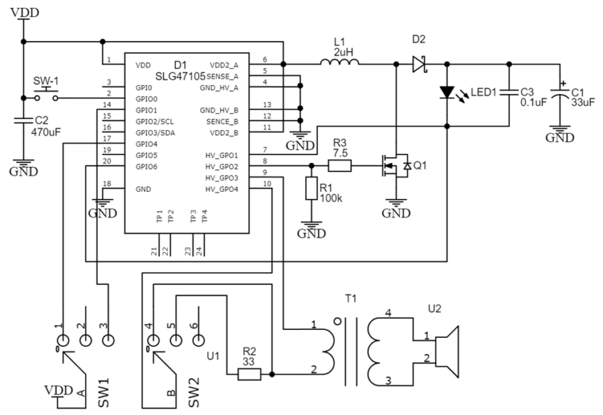
The Full Circuit Schematic is shown in Figure 2.
The GreenPAK design is shown in Figure 3. The complete design file can be found here. It was created in free GUI-based GreenPAK Designer software – a part of Go Configure Software Hub.
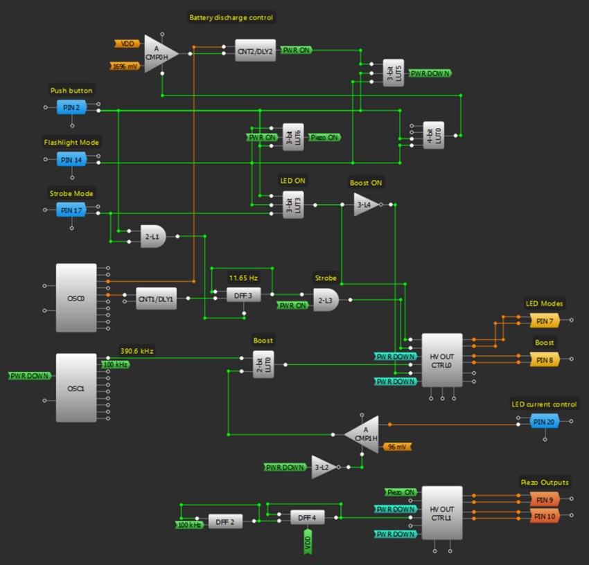
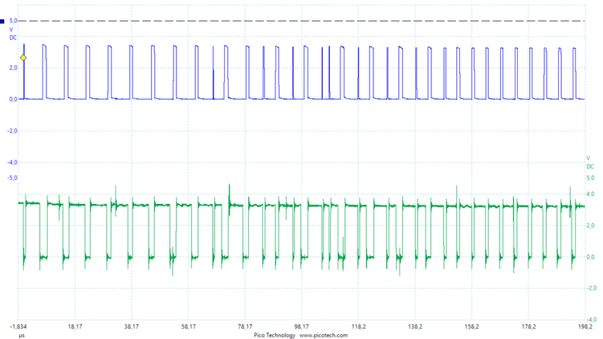
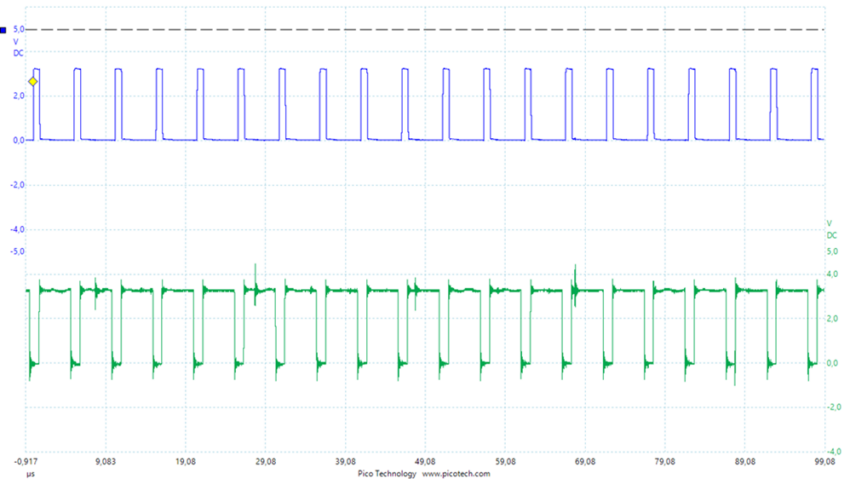
The 390.6 kHz signal with a 50% duty cycle is created by OSC1 and goes to the 2-bit LUT0, which controls the Booster circuit through the HV PIN 8. When the maximum LED current of 700 mA is reached, the ACMP1 sets the 2-bit LUT0 to 0 and pulls down the HV PIN 8 keeping the current through the LED at the same level. It should be noted, that the external MOSFET must be selected with the lowest possible gate threshold voltage high enough current. For example IRLL3303. The results of Boost can be found in Figure 4 and Figure 5. The HV PIN 8 is represented in blue and the ACMP1 is in green.
The necessary LED mode is selected by 3-bit LUT3 and DFF3. These signals go to HV PIN 7 of the HV OUT CTRL0 which is configured as a Half-Bridge and acts as a switch for the LED. So, the LED is ON when PIN 7 is LOW and vice versa. Also, the internal low-side MOSFET (PIN 7) is used as a current sensor. Its RDS On is about 150 mOhm which is perfect for our purpose.
2. Dog Repeller Mode
The Dog Repeller mode includes two parts the Ultrasonic signal at full power and the LED strobe light.
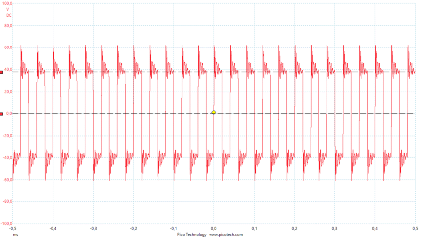
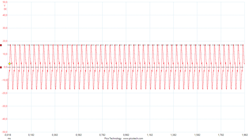
The OSC1 generates the 100 kHz signal which goes through DFF2 and DFF4 and decreases to 25 kHz. Then this signal goes to PH input of HV OUT CTRL1, which is configured as Full Bridge. The Enable signal Piezo ON is generated by 3-bit LUT6 to be HIGH only when Dog Repelling Mode or Dog Training Mode is selected. To achieve the necessary amplitude the 4:40 voltage transformer is used. PIN 9 and PIN 10 are connected to the primary winding and the piezo element is connected to the secondary winding (see Figure 2). The resulting signal in the piezo element is a ~37 V amplitude ultrasound signal (Figure 6).
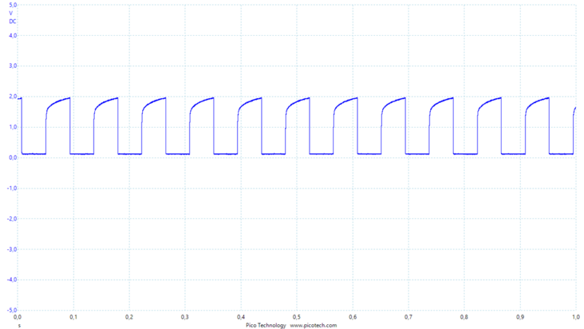
The LED strobe light is used to increase the dog`s disorientation. In this case, the 3 W LED is connected to PIN 7 of HV OUT CTRL0 with an input of 11.65 Hz. The resulting LED signal is shown in Figure 7.
3. Dog Training Mode
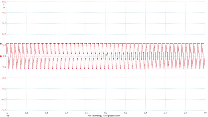
The Dog Training mode includes a 25 kHz signal with ~17 V amplitude when the battery is charged (4.1 V) and ~12 V when the battery is discharged (3.1 V). The additional 33 Ohm resistor is connected to PIN 9 of the primary winding of the voltage transformer and limits the current to ~80 mA to decrease the power of the piezo output signal (see Figure 8 and Figure 9).
4. Flashlight
In the Flashlight mode, the DFF3 sets the Enable signal OE0 of the HV OUT CNTR0 to HIGH, and the 3-bit LUT3 set the IN0 to LOW, so the output of PIN 7 is continuously LOW and the LED is continuously ON.
5. Battery Discharge
As the device is powered by a Li-ion battery, for example, a 18650 cell, there is a need to control the discharge level to prevent cell damage (assuming the battery does not have its own protection circuit). The comparator ACMP0 monitors the VDD level and if the voltage is less than 3072 mV the circuit is cut off. When the Dog Training Mode or Dog Repeller Mode is selected and the push button is not pressed, comparators ACMP0 and ACMP1, HV OUT CTRL0, HV OUT CTRL1, and OSC1 are in Sleep Mode thus consuming close to 0 current. The device is considered turned off when the switch is in the middle position and the push button is not pressed.
Conclusion
The article describes how to configure the HVPAK to create a Dog Chaser. The results prove that the circuit works as expected, and the HVPAK is capable of acting as the control module for the piezo element and the powerful LED.
The Dog Chaser has three modes. The Dog Repeller mode is powerful ultrasonic and strobe light signals that disorient the dog. The Dog Training mode is a lower-power ultrasonic signal which helps to train the dog. The last mode is a powerful flashlight.


