Using OV7670 Camera Sensor With Arduino
Developing a hardware project became much easier thanks to the growing number of the various sensors and actuators modules, which give you the ability to shift your ideas into a wider range of applications. This tutorial presents the steps of how to use OV7670 Camera Sensor Module STM32 with Arduino.
Developing a hardware project became much easier thanks to the growing number of the various sensors and actuators modules, which give you the ability to shift your ideas into a wider range of applications. This tutorial presents the steps of how to use OV7670 Camera Sensor Module STM32 with Arduino.
To follow the tutorial, you will need these parts:
- Arduino Uno Board and USB
- OV7670 Arduino Camera Sensor Module STM32
- Resistor (2x10K & 2×4.7K)
- Breadboard
The OV7670 image sensor is a small size, low voltage, single-chip VGA camera and CMOS image processor for all functions. It provides full-frame, sub-sampled or windowed 8-bit images in various formats, controlled through the Serial Camera Control Bus (SCCB) interface.
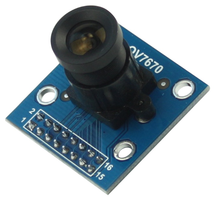
The camera module is powered from a single +3.3V power supply, and external clock source for camera module XCLK pin. The OV7670 camera module built-in onboard LDO regulator only requires single 3.3V power and can be used in Arduino, STM32, Chipkit, ARM, DSP, FPGA and etc.
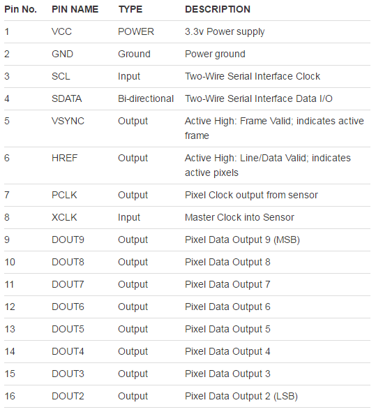
This is pin definition table of the module:
OV7670 module specification:
- Optical size 1/6 inch
- Resolution 640×480 VGA
- Onboard regulator, only single 3.3V supply needed
- Mounted with high quality F1.8 / 6mm lens
- High sensitivity for low-light operation
- VarioPixel® method for sub-sampling
- Automatic image control functions including: Automatic
- Exposure Control (AEC), Automatic Gain Control (AGC), Automatic White Balance (AWB), Automatic
- Band Filter (ABF), and Automatic Black-Level Calibration (ABLC)
- Image quality controls including color saturation, hue, gamma, sharpness (edge enhancement), and anti-blooming
- ISP includes noise reduction and defect correction
- Supports LED and flash strobe mode
- Supports scaling
- Lens shading correction
- Flicker (50/60 Hz) auto detection
- Saturation level auto adjust (UV adjust)
- Edge enhancement level auto adjust
- De-noise level auto adjust
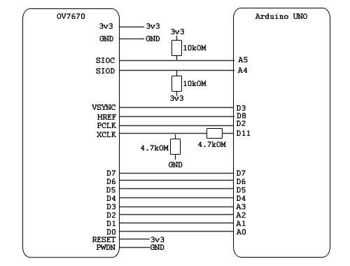
The connection between the module and the Arduino uses 6 analog pins and 8 digital pins, and they have to be connected as shown in this figure:
The software requirements are the Arduino IDE and Java Development Kit (JDK). To run the project, you have to execute a java code through the command line. The script will search for images received from Arduino and then saves them on the PC.
Source code, additional needed files, and setting up instructions are all available at the tutorial page.


Your diagram shows 18 pins, but your table (and my camera) only have 16. Can you adjust the diagram to be consistent, please?
If your camera module has 16 pins then use only those and it should work. The confusion caused as some boards have 2 additional pins for RESET and POWER DOWN.
the cmd shows
Error: Could not find or load main class code.SimpleRead
please help sir
Have you included any possible libraries on the code?