Bootstrap Circuit in the Buck Converter explained
This application note explains the step-up circuit using a bootstrap capacitor. In buck converters, this circuit is used when the high-side switch is the N-ch MOSFET.
This application note explains the step-up circuit using a bootstrap capacitor. In buck converters, this circuit is used when the high-side switch is the N-ch MOSFET.
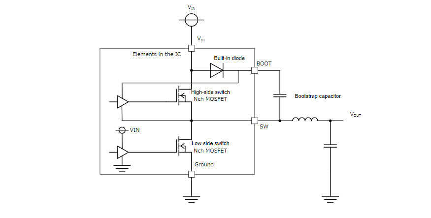
The configuration of the circuit in proximity to a buck converter depends on the polarity of the high-side switch.When a P-ch MOSFET is used for the high-side switch, there are advantages over using a N-ch MOSFET, such as the capability of driving the switch with input voltage VINas the gate voltage, as well as voltage reduction and obtainment of the maximum duty. On the contrary, the use of a P-ch MOSFET requires a larger chip area for passing the same current.The use of an N-ch MOSFET for the high-side switch requires a gate voltage of VIN+ Vth (threshold voltage of the N-ch MOSFET) or higher. A step-up circuit is required because the gate voltage is higher than VIN. This circuit is configured with an internal diode and an external bootstrap capacitor (charge pump type). The total cost, including the cost of the external bootstrap capacitor, can be lowered because the chip area can be reduced compared with the P-ch MOSFET, as mentioned above.
Bootstrap Circuit in the Buck Converter explained – [PDF]


