This Solar Buck-Boost Module Enhances Solar and USB Power Management for Embedded Systems
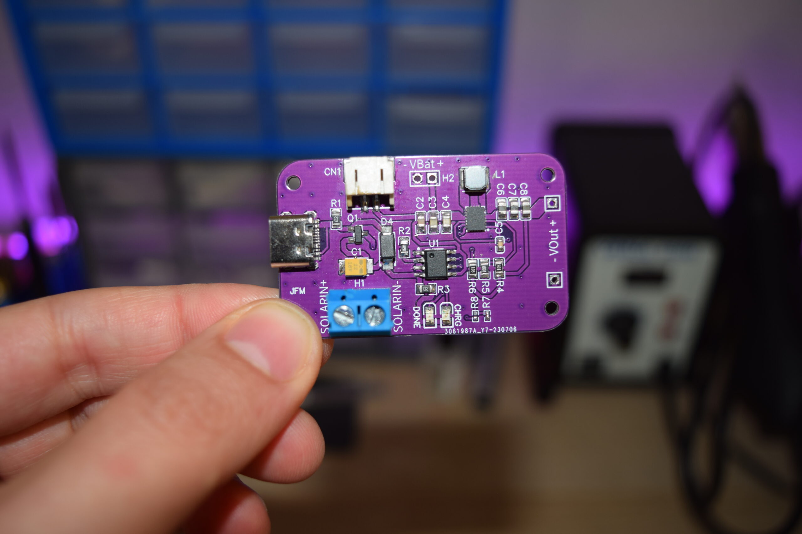
Juan Flores' Solar Buck-Boost Module is designed to charge a lithium-polymer battery using either a solar panel or USB power, providing a constant output voltage for noise-free power management for low-power applications. This board is designed to automatically switch between solar and USB power, without interrupting the attached load.
Juan Flores’ Solar Buck-Boost Module is designed to charge a lithium-polymer battery using either a solar panel or USB power, providing a constant output voltage for noise-free power management for low-power applications. This board is designed to automatically switch between solar and USB power, without interrupting the attached load.
This project is a module that allows charging a Li-Po battery from two different energy sources and provides a constant output voltage independent of the battery voltage, with minimal losses to ensure long-lasting operation in low-power applications. It works correctly with a solar panel, hence its name.
The board is very well-designed, it has all the necessary connections to connect the battery, solar power, and the load, spread across the whole board. The board also features set resistors through which you can adjust the output voltage from 2.5V to 5V. It also has different power-saving modes, but what it lacks is protection.
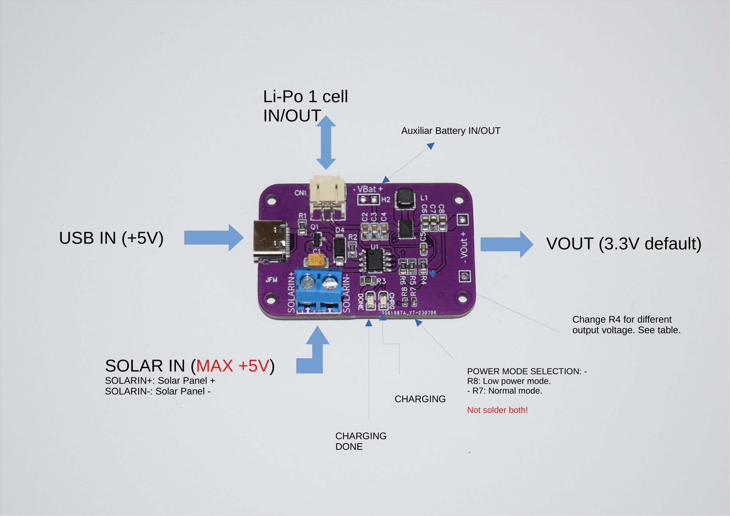
In the above image, you can see all the major connection points of this board. All the inputs and outputs are listed here. The board marking also mentions the Resistor R4 through which you can set the output voltage of this board: a 750K resistor for 2.5V, 1M for 3.3V, 1.1M for 3.6V, 1.43M for 4.5V, and 1.6M for a 5V output. This feature allows for customizable voltage settings, catering to various power requirements.
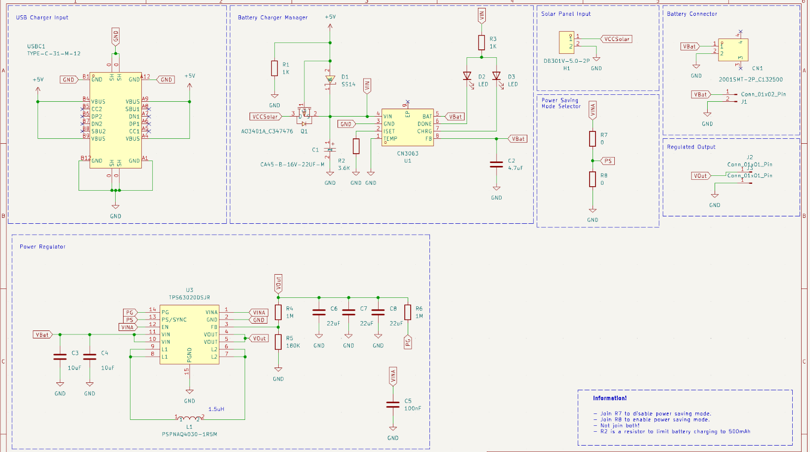
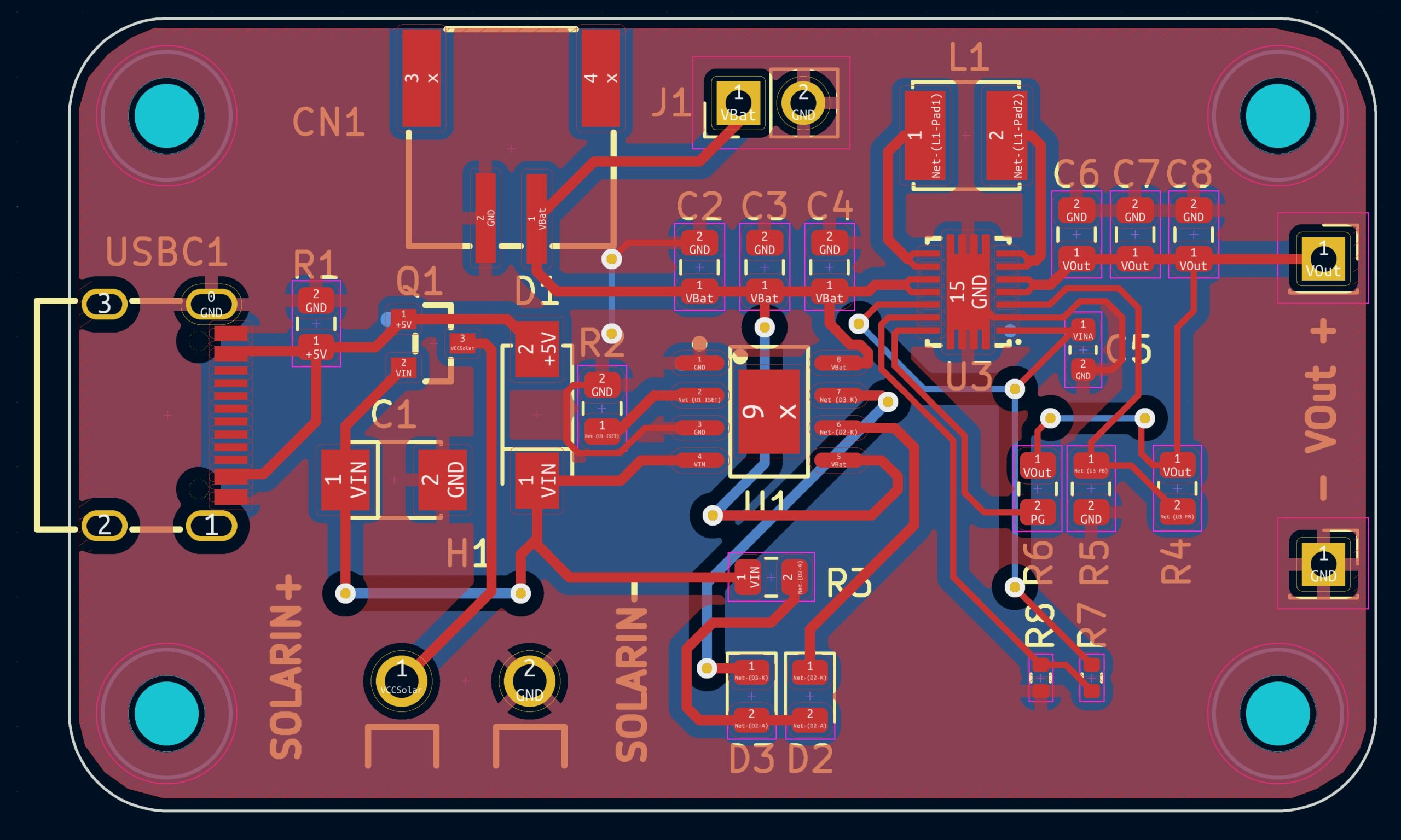
The project is completely open sourced so all the necessary documentation, like the Schematic and the Layout of this project, is available for use. looking at the schematic we can see that the project is built around two major components those are the Consonance Electronics CN3063 lithium-polymer charging chip and a Texas Instruments TPS63020 which is a High Efficiency Single Inductor Buck-boost Converter with 4-A Switches, to regulate the output voltage.
The charging mechanism in this circuit functions like an N-type MOSFET, where the solar panel connects to the drain and the USB to the gate. When USB power is available, it automatically charges the battery. If there’s no USB power, the circuit switches to draw power from the solar panel for charging.
In his Hackday Article Flores mentions,
“It would work with solar panels from 4.5V to 6V, but ideally, a maximum of 5V should be used. Also, the charging speed depends on the panel’s power. The one I use is 0.2W at 5V, meaning it generates 40mAh at full performance, so it would take 10 hours in full sun to charge a battery like the one in the video (500 mAH). What I mean is that when choosing the panel, these data should be considered.”
You can find a detailed description of the project on Hackaday.io. Additionally, the KiCad project files and schematics are accessible on GitHub, though the specific licensing details are not mentioned.


